Line Following @ DPS Monarch Tech Fest
Introduction
Since 2020, DPS Monarch School (Doha, Qatar), has held a Tech Fest, celebrating today’s technological advancements through various competitions and events.
In the years 2023 – 2024, as well as the 2024 – 2025, I have been lucky to be selected for this gathering, in the line following robot event.
Before I go on with the event itself, I would like to talk about our line following robot, and line following in general.
Year 1
June 2023 was when I was first introduced to the world of line following. When I first received the opportunity to participate, I had thought, ‘How hard can it be?’ And later, after some block coding with the mBot2, along with my other 3 team members, I found out that I was right.
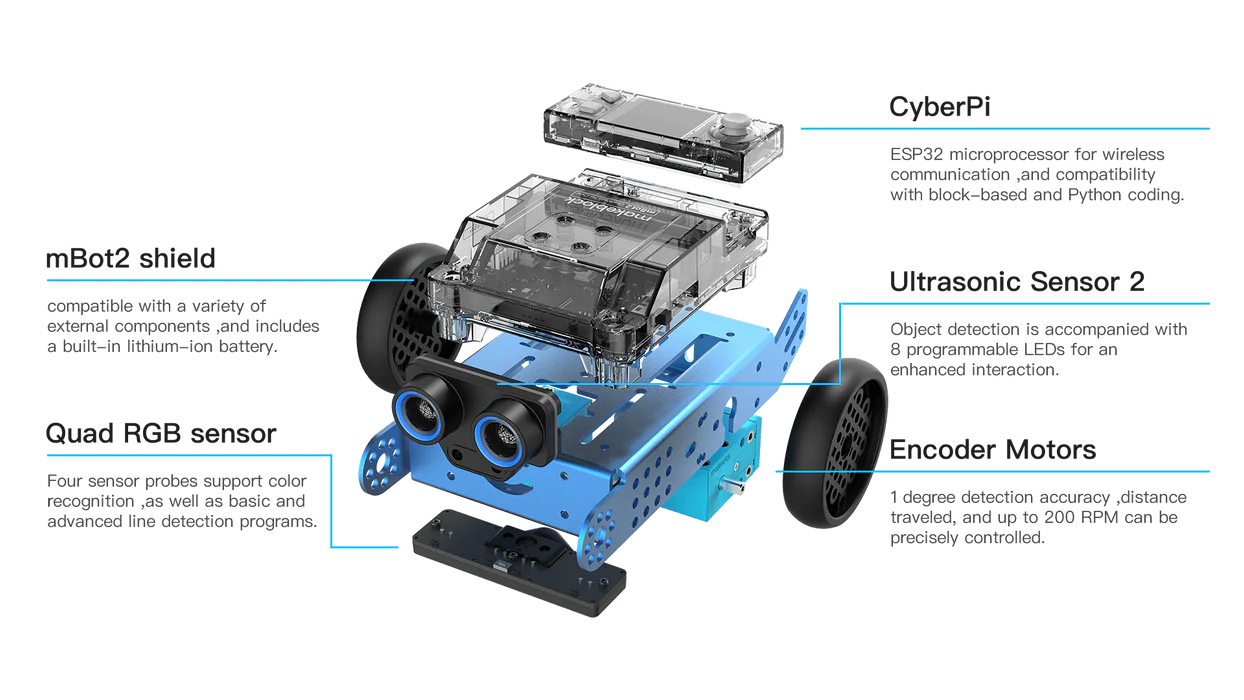
Using a quad RGB sensor that turned the robot whenever the line got to the edge proved to be a robust method. Hence, we had a robot that could follow a line… but the story wasn’t over.
Humans are always obsessed with making something stronger, faster, better, and this spirit is good. This spirit is what allows us to grow, technology to advance and solve problems better. In our case, if we wanted to win the competition, the robot had to not only follow the line, but it must do so quickly.
No problem! Increase the speed! And this approach worked, of course… until it didn’t. Because, as we realized, there is a huge tradeoff between speed and accuracy.
If you want to get a little technical, then listen up. The RGB sensor updates once every moment. This could be every 20 milliseconds, or any other amount of time (you’ll have to do some research on that specific RGB sensor). But after the quad sensor detects a change in state (by state I mean which of its 4 sensors detect a line), it must relay that to the hub. This relay also takes time, which is termed the latency. Then there is also the latency between the hub telling the motors to react accordingly and the motors receiving that signal.
You probably know by now where this is going. The latency time remains constant even as our speed scales up. This means our accuracy will suddenly plummet, because at quick speeds, there won’t be enough time to react before the robot goes off the line. Is this a hardware problem? Kind of. Did that stop us? Well…
This was our first time of course, so I didn’t know anything too fancy. But with some thinking, I thought of this solution:
The RGB sensor is a quad sensor, which means there are 4 individual sensors that can either be on or off. They can be represented as 0000 when nothing is detected or 1111 when every sensor detects a line. This means that a robot following a line would have a sensor pattern of 0110.
.png)
Now comes the magic. If the line bends right, for example, the sensor will either be 0011 or 0001 depending on how far the line bends. If the line bends slightly, we can continue using our normal turning speed, but in the case of a sharper bend (0001), we can use a higher turning speed. Using this logic, the robot can slow down and turn faster if it is just about to go off the edge.
We didn’t have much time the first year, so we settled for this plan (because we had nothing better) and adjusted the values to try and maximize the speed without giving away accuracy.
Fast forward a few days to the event itself – Monday, 12th of August 2023. Monarch Tech Fest 4 – Intellitronix. Hosted in the school’s amphitheater, we were first treated to some spectacular displays from the school choir and dancers. We were also treated to speeches from some students, the principal and the guest speaker. Finally, the time came to disperse for the events.
The line following event, hosted in the amphitheater itself, consisted of the various schools, represented by four students and a robot, and two equal lines. One was for practice and one for the race.
Schools were to be ranked based on the time it took for their robot to finish the track. Touching the robot at any point of time would add 10 seconds. If the robot went off track, we had to pick it up and put it at the place where it last was on the line (and this means +10 seconds).
We had around ten minutes of practice time before they began randomly picking the schools to start their race.
After the first time on the practice line, we immediately faced two problems:
1. The line was thinner than we had practiced for and coded based on. This wasn’t that big of an issue as all we needed to do was change the turning speed values. However, we only had 10 minutes to do so, and if not fixed, the robot might over or under steer, which can lead to it going off the line.
2. We had not anticipated the fact that the line would have any intersections (our practice line back at the school was very simple). This meant that the robot would possibly repeat a part of the line instead of going forward.
After practicing and adjusting our values as best as we could with the time we had, we had to move on to the race. As fate would have it, the robot did not make the intersection and we had to put the robot back, costing us 10 seconds. Despite this setback, we still managed to make 2nd place.
Year 2
Now fast forward to next year. I’d finished my class 9 exams, dug myself deeper into programming and computer science, and was feeling ready to take the gold. My team had also changed, with two of the members getting replaced.
Confidently, I searched the school computer we used last year for our old code… only to find that it wasn’t there. So reluctantly, I programmed a simple version of the code again, just so we weren’t sitting at a blank page.
I also did my research this time, and I found myself a potential solution: PID controlled loops. ‘What is that?’ you might ask. PID is a feedback loop that determines the right amount to steer using proportional control, integrals and derivatives. Of course, I did not do my research enough to fully understand this at the time. I thought only of the ‘proportional control’ part of PID.
This, however, was a revolutionary concept to me regarding the whole ‘line following’ idea. The only problem was that I didn’t know quite yet how to implement it.
You see, the way a proportional control loop works is by taking the distance between the middle of the sensor and the line (the error) and multiplying it with a constant (you need to experiment with different values) to determine the right amount to steer. At first, I didn’t know how to get the error, so I tried some changes to the code, like last year.
Eventually, I figured out how to output the error from the sensor. After implementing a simple proportional control loop, I was surprised to see that it worked like magic. The robot was practically glued to the line.
The only problem, however, was that this did not scale well at all at higher speeds. I tried messing around with that constant I mentioned earlier to no avail. The only thing that worked was a manual override at higher error values, which, to be honest, kind of defeated the whole purpose of proportional control itself.
I wonder now, if I had properly implemented the PID loop, if I would have been able to get it to work at high speeds.
Anyway, the robot was doing fine with this new code, and was more robust against intersections – we had new, more complex practice lines at our school to test it. The robot also managed to put a more consistent performance across all the lines, which was encouraging to see.
We were pretty much ready, and so spent the rest of the time fine-tuning the values and adding some personal touches. We also tried extending the RGB sensor outwards. The day of the event approached…
Monarch Tech Fest 5 – TechGlanz. On Thursday, 13th June 2024, we once again headed over to the amphitheater. After the introductory session, like last year's, we wasted no time in getting to the practice line. This time, around 20 schools were participating.
One thing we noticed was that the line was the same as last year’s as well, so this would be a true test to see how much we improved. This time, they also gave each team two chances, the best of which would be selected.
After a well-deserved show-off in the practice line, we went for the race and crushed it. The other teams were either slow or their robots acted erratically, this included DPS Monarch’s team, which had won the previous years. Though I admit, this small victory might’ve gone to our heads.
For our second time, we decided to push the robot’s speed – but not to the limit. After shaving down our previous record, we felt satisfied.
As fate would have it again, DPS Monarch’s team won this time again. I didn’t see their robot do the track, but it could be assumed they used code similar to ours.
Our code was pretty good. At that time, I thought it was the best that could be achieved. Now, I realize we missed an important part of the loop – I’ll get to that in a bit. The point is, each year we think we have done our best, we have reached the peak, but there will always be something better, something faster, something stronger, because there will always be people seeking it.
Year 3?
So now we fast forward to next yea- well, unfortunately, I can’t participate in season 6 of this event. I am, in fact, in Canada, and though that hasn’t stopped my love for robotics, I cannot help my team in the next iteration of our line following robot.
So, what is a PID feedback loop? Well, this lesson explains it very clearly, but I can provide a quick summary.
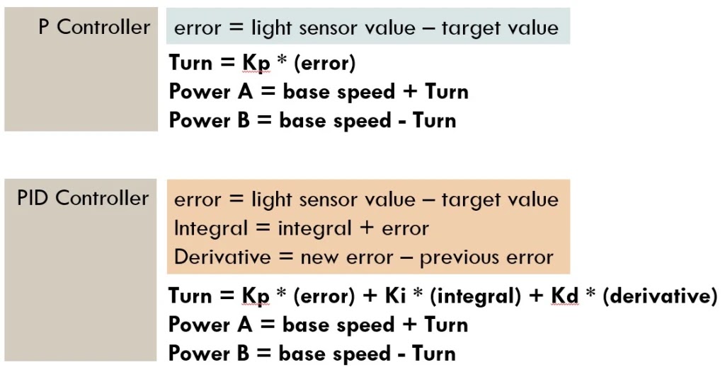
PID, as I said before, is a feedback loop using proportional control, integrals and derivatives. That is, in fact, how it got the name. A feedback loop is basically a constant cycle of sense, adjust and repeat.
A proportional control loop (like the one I implemented) works by multiplying the error with a constant value to find the value. However, this is only one part of the formula.
The integral part finds the past turning history of the follower. We then scale this value using another constant.
The derivative part finds the rate of change of error, which is then scaled by a third constant.
So far, we have three different values, all scaled. To find the turning value, we sum these three values together.
Here is the pseudocode, taken from the lesson:
1. Take a new light sensor reading
2. Compute the “error”
3. Scale error to determine contribution to steering update (proportional control)
4. Use error to update integral (sum of all past errors)
5. Scale integral to determine contribution to steering update (integral control)
6. Use error to update derivative (difference from last error)
7. Scale derivative to determine contribution to steering update (derivative control)
8. Combine P, I, and D feedback and steer robot
In conclusion, I would like to revisit my first thought when I came across this challenge: ‘How hard can it be?’ This serves as a reminder that even the (seemingly) simplest of tasks, when faced with human perseverance and ambition, can always be done in a better way.

I would someday like to implement my own PID algorithm (or one of the many other feedback loop algorithms used in industrial applications) and perhaps improve upon it further – hopefully with some self-designed hardware.

Comments
Post a Comment